doi: 10.62486/agmu2024207
ORIGINAL
Verification of a method for implementing a closed-loop control system for an electromechanical system with distributed parameters in the mechanical part
Verificación de un método para implementar un sistema de control de lazo cerrado para un sistema electromecánico con parámetros distribuidos en la parte mecánica
A.
P. Korneev1,
G. S.
Lenevsky1,
Yitong Niu2,
Abdullayev
Vugar3 ![]() *
*
1Department of Electric Drive, Faculty of Electrical Engineering, Belarusian-Russian University. Mogilev, Belarus.
2Department School of Industrial Technology, University Sains Malaysia. George Town, Malaysia.
3Azerbaijan State Oil and Industry University, Computer engineering.
Cite as: Korneev AP, Lenevsky GS, Niu Y, Vugar A. Verification of a method for implementing a closed-loop control system for an electromechanical system with distributed parameters in the mechanical part. Multidisciplinar (Montevideo). 2024; 2:207. https://doi.org/10.62486/agmu2024207
Submitted: 08-06-2024 Revised: 22-09-2024 Accepted: 11-12-2024 Published: 12-12-2024
Editor: Telmo
Raúl Aveiro-Róbalo ![]()
Corresponding Author: Abdullayev Vugar *
ABSTRACT
A research facility has been developed for verifying a method for implementing a closed-loop control system along an intermediate coordinate for an electromechanical system with distributed parameters in the mechanical part using an observing device. The scheme of the experimental stand with a detailed description is given. The mechanical parameters of the experimental stand are given. As a system with distributed parameters, a spring with a low coefficient of elasticity was used in the stand, inside which a string is stretched to avoid the effect of sagging. A distinctive feature of a system with distributed parameters is the presence of forward and backward branches of a one-dimensional system with distributed elasticity. The small coefficient of elasticity of the spring provides resonance phenomena at low frequencies, which is observed in spatially extended systems with distributed parameters. A thyristor converter is used to control the rotational speed of the electric motor in the experimental stand. A photo of the converter with the control circuit is shown. The implementation of the sinusoidal control law is provided by a crank mechanism, its scheme is presented. An electrical circuit diagram for providing power to the experimental stand is presented. A photograph of the appearance of the electrical part of the stand is presented. The range and accuracy of a set of voltage and current measuring devices are indicated. To obtain information about the motor current, a software and hardware complex is used. The description of the software and hardware complex is presented. A control program has been developed for making measurements on four voltage channels. The procedure for determining the coefficient of proportionality between the voltage of the reference and the oscillation frequency of the system with distributed parameters for the experimental setup and its value are presented. The feedback signal is connected using a switch located on the experimental stand.
Keywords: System with Distributed Parameters; Resonant Frequency; Experimental Stand; Coefficient of Proportionality.
RESUMEN
Se ha desarrollado un instrumento de investigación para verificar un método de implementación de un sistema de control de lazo cerrado a lo largo de una coordenada intermedia para un sistema electromecánico con parámetros distribuidos en la parte mecánica utilizando un dispositivo de observación. Se presenta el esquema del soporte experimental con una descripción detallada. Se presentan los parámetros mecánicosb del soporte experimental. Como sistema con parámetros distribuidos, se utilizó en el soporte un resorte con un coeficiente de elasticidad bajo, dentro del cual se estira una cuerda para evitar el efecto de pandeo. Una característica distintiva de un sistema con parámetros distribuidos es la presencia de ramas hacia adelante y hacia atrás de un sistema unidimensional con elasticidad distribuida. El pequeño coeficiente de elasticidad del resorte proporciona fenómenos de resonancia a bajas frecuencias, lo que se observa en sistemas espacialmente extendidos con parámetros distribuidos. Se utiliza un convertidor de tiristores para controlar la velocidad de rotación del motor eléctrico en el soporte experimental. Se muestra una foto del convertidor con el circuito de control. La implementación de la ley de control sinusoidal se proporciona mediante un mecanismo de manivela, se presenta su esquema. Se presenta el esquema eléctrico de alimentación de la estación experimental. Se presenta una fotografía del aspecto de la parte eléctrica de la estación. Se indican el alcance y la precisión de un conjunto de dispositivos de medición de tensión y corriente. Para obtener información sobre la corriente del motor se utiliza un complejo de software y hardware. Se presenta la descripción del complejo de software y hardware. Se ha desarrollado un programa de control para realizar mediciones en cuatro canales de tensión. Se presenta el procedimiento para determinar el coeficiente de proporcionalidad entre la tensión de referencia y la frecuencia de oscilación del sistema con parámetros distribuidos para la configuración experimental y su valor. La señal de retroalimentación se conecta mediante un interruptor ubicado en la estación experimental.
Palabras clave: Sistema con Parámetros Distribuidos; Frecuencia de Resonancia; Estación Experimental; Coeficiente de Proporcionalidad.
INTRODUCTION
Numerous objects in various fields of technology are systems with distributed parameters (SDP). These include long power lines, pipelines for pumping water and oil, objects that include long rods, for example, in drilling - a string of pipes, in deep-well pumping installations - a rod, in lifting mechanisms - a cable and a rope, etc.(1,2)
Elastic deformations of the links of mechanical transmissions are one of the factors that impede the increase in the efficiency of control of electromechanical control objects.(3,4)
An increase in the speed of modern machines with a simultaneous increase in spatial dimensions, an increase in requirements for the accuracy of movements, the emergence of fundamentally new designs determines the conditions under which it is impossible to create high-quality control systems for machines and mechanisms without taking into account the properties of the mechanical part of the electric drive. The lifting unit is a non-stationary electromechanical system with distributed parameters.(5,6,7)
The main pliable element of the system is the load branch of the rope, the stiffness of which is much less than the stiffness of other links. Therefore, the behavior of the system can be estimated by design schemes, considering the rope only as an elastic element.(8,9,10)
Elastic deformations arising in systems with distributed parameters have a great influence on the operation of electric drives.(11) An insufficiently accurate mathematical description of such equipment leads to large errors in the analysis and synthesis of control systems, to a decrease in the accuracy of work, to a loss of stability of the electric drive, and in the most unfavorable cases, to the destruction of the installation. When describing, the following assumptions are made: the mechanical part is idealized as a rod experiencing longitudinal vibrations, and concentrated masses are represented as infinite density jumps.(11)
Main part
The stand location can be horizontal, vertical or inclined. As an example, the horizontal installation location is considered (figure 1):
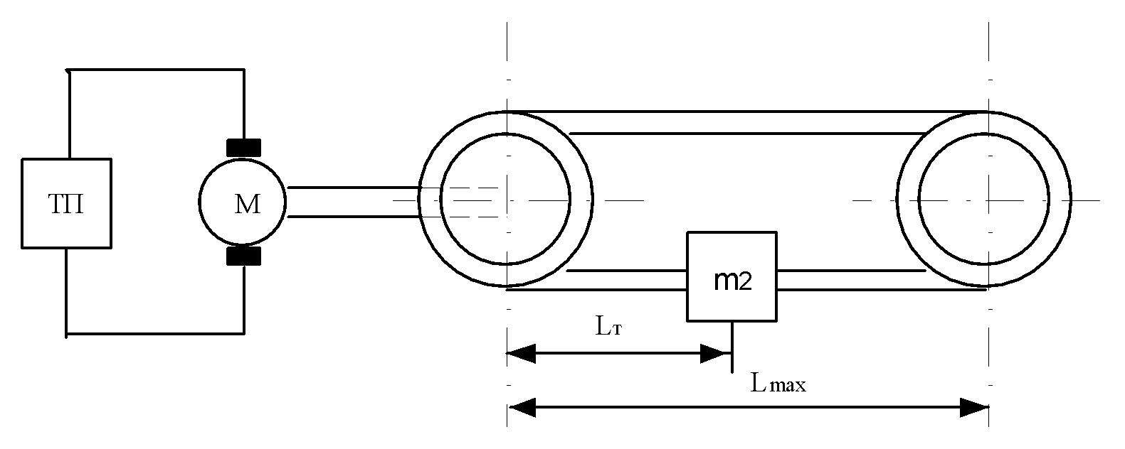
Figure 1. Scheme of the experimental stand
The experimental setup consists of: TП – thyristor converter, M – electric motor, two metal disks with a spring stretched between them, which is SDP.
Mechanical parameters of the setup: relative mass of the first disk and the electric motor μ1 = 0,87, relative mass of the second disk μ2 = 0,46, oscillation propagation velocity a = 23,5 m/s, distance between disk centers Lmax – 7 m. The moving mass during initial studies m2 = 0.
A distinctive feature of the SDP under study is the presence of direct and reverse branches of a one-dimensional system with distributed elasticity.
A spring with a low elasticity coefficient is used as SDP in the setup, inside which a string is stretched to prevent sagging.
The low elasticity coefficient of the spring ensures resonance phenomena at low frequencies, which is observed in extended SDP. To drive the SDP, electric motor PBST-22 DC with a power of 950 W is used.
The rotation speed of the electric motor shaft M is regulated by changing the supply voltage. For this purpose, the thyristor converter ET6 is used in the stand, connected to AC network of 380 V, with a frequency of 50 Hz.
A shunt RS1, connected in series to the winding of the electric motor armature, is used as a sensor that determines the instantaneous value of the current flowing through the armature of the electric motor.
The voltage supplied to the armature of the electric motor is proportional to the reference signal (varies from 0 V to 10 V) and is regulated by a potentiometer (figure 2).
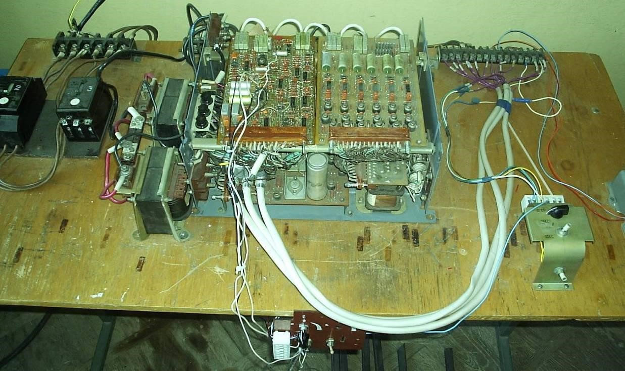
Figure 2. Photo of converter with control circuit
The reference action for SDP is the electromagnetic torque of the electric motor M, the change of which according to the sinusoidal law is ensured by means of a crank mechanism (figure 3).
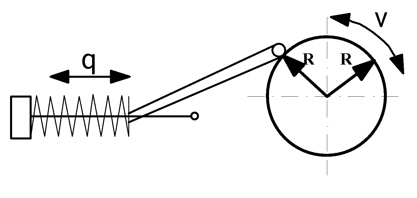
Figure 3. Photo of converter with control circuit
To provide power supply to the experimental setup, an electrical circuit diagram was designed figure 4.
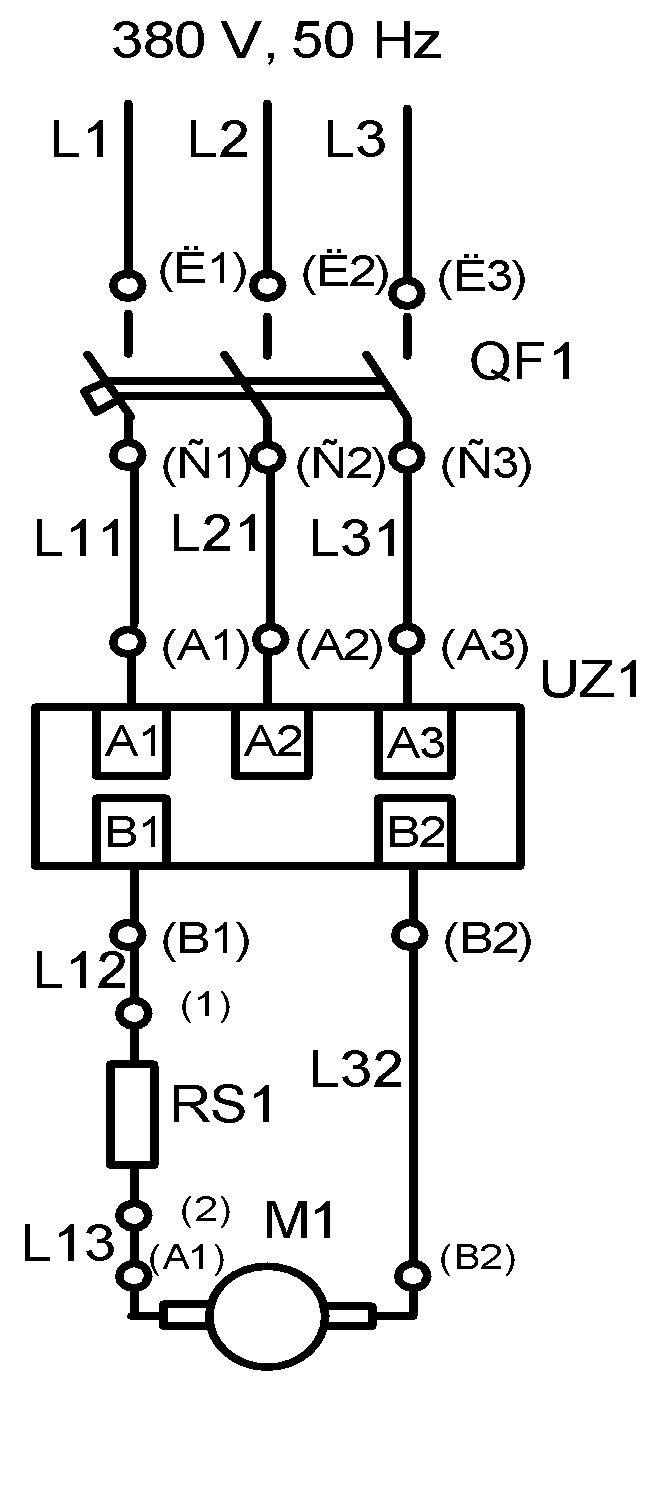
Figure 4. Electrical circuit diagram of the stand
The electrical stand circuit diagram consists of: QF1 – circuit breaker, UZ1 – thyristor converter, RS1 – current sensor, M1 – electric motor.
A photograph of the external appearance of the electrical part of the stand is shown in figure 5.
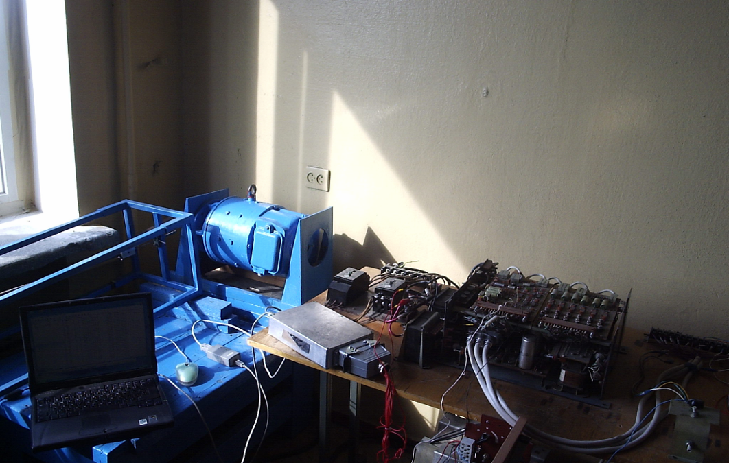
Figure 5. Photo of the appearance of the electrical part of the stand
The set of measuring devices ensures measurement and storage of data:(12,13)
· Voltage in the range from -400 V to +400 V with an accuracy of at least 0,1 %.
· Motor armature current in the range from -10 A to +10 A with an accuracy of at least 0,1 %.
· Voltage taken from the tachogenerator in the range from 0 V to +2,5 V.
The connection of the measuring system with a personal computer serves to simplify further processing of the received information and storage of all received data.
To obtain a specified measurement accuracy in a digital data acquisition system, it is necessary to have analog-to-digital converters with a number of digital digits of at least 10.(14)
The sampling frequency in accordance with the discrete Nyquist theorem must be at least twice the frequency of the fastest changing signal - (the ratio of the sampling frequency to the cutoff frequency of the system for the possibility of signal reproduction must be at least two).(15) Since the frequency of the supply voltage, and accordingly the current, is 50 Hz, the sampling frequency must be at least 100 Hz.
A hardware and software complex are used to obtain information about the motor current. The hardware part is represented by a current sensor.
The voltage taken from tachogenerator is directly proportional to the speed of rotation of the electric motor shaft and is used to implement the simplest single monitoring device.(16)
The hardware and software complex have four galvanically isolated analog inputs for measuring high-voltage voltage (input voltage range from +600 V to -600 V), as well as one analog input for measuring low-voltage voltages taken from the shunt (input voltage range on the measuring shunt from +150 mV to -150 mV).
The capacity of analog-to-digital converters for all channels is 12. The element that processes information in the module is the Fujitsu MB90F543 microcontroller. The Softune Workbench for FR-microcontroller programming environment is used to develop control programs. The controller is programmed using the StrimShell - StrimServer software suite from STREAM LLC.(17)
The developed control program allows measurements to be taken on four voltage channels with a frequency of up to 4 kHz. The conversion data is generated by a CAN frame, which is subsequently transmitted via the CAN bus. Then they are converted by a CAN-USB converter and redirected to a personal computer, where they can be further processed.
The StrimServer and CANMonitor software suite is the software part of the complex, which allows recording and storing information received from the sensor module in real time.
Formulas
The angular speed of rotation of the electric motor shaft is directly proportional to the reference voltage
![]()
k1 - proportionality coefficient between the frequency of oscillations of SDP and voltage of the task.
ω – angular velocity of motor rotation.
Uз – reference voltage.
The angular velocity of the electric motor shaft as the reference voltage requires more precise measurement, therefore the proportionality coefficient between the frequency of oscillations of the SRP and the reference voltage is determined.
The relationship between the reference voltage and the frequency of oscillations of the system with distributed parameters is directly proportional:
![]()
Where:
f – frequency of oscillations of SDP.
K – proportionality coefficient.
Uз – reference voltage.
The proportionality coefficient is calculated as follows:
![]()
Where:
T – period of oscillations of the SDP.
The proportionality coefficient is determined empirically using the following formulas.
![]()
Where:
L – length of circumference of drive station.
R=0,05 м – radius of drive station.
![]()
Where:
V – linear velocity of mass rotation 1.
After transformation (2) – (5) final calculation formula for determining the proportionality coefficient is obtained:
![]()
As a result of calculations for this stand get K=0,1483 (V*s)-1.
The feedback signal is connected using a switch in control system located on the stand. This allows you to study of SDP with and without connecting feedback.(18)
The measurement of oscillation amplitude at each frequency is performed visually using a ruler and values are recorded in a table for further calculations.
The accuracy of measurements is low, but it is sufficient to check operability of control system synthesis technique of SDP.
CONCLUSIONS
1. A test bench for testing synthesis methodology of SDP control system has been developed.
2. Sinusoidal control law is implemented by a crank mechanism.
3. Coefficient of dependence between the task voltage and SDP oscillation frequency has been calculated.
BIBLIOGRAPHIC REFERENCES
1. Zames, G. On spectral mapping, higher order circle criteria and periodically varying system. IEEE Trans / G. Zames, R. Kallman - Automat. Control vol. AC-15, 1970. - P. 649-652
2. Sarangapani, Jagannathan. Neural network control of nonlinear discrete-time systems / Jagannathan Sarangapani – Taylor & Francis, vol. AC-15, 2006. - P. 649-652
3. Rassudov, L. N. Electric drives with distributed parameters of electromechanical elements / L. N. Rassudov, V. N. Myadzel - L.: Energoatomizdat, Leningrad. ot-nie, 1987.– 144 p.
4. Brocket, R. W. The status of Stability Theory for deterministic systems / R. W. Brocket - IEEE Trans - Automat. Control, vol. AC-11, no. 3, 1966. - P. 596-606
5. Ortega, R. Almost periodic equations and conditions of Ambrosetti / R. Ortega, M. Tarallo – Prodi type. Academic Press, N. Y. and London, 1973, 217 P.
6. Butkovsky, A. G. Control methods for systems with distributed parameters / A. G. Butkovsky - M.: Nauka, 1975. - 230 p.
7. Nagendga, K.S. Frequency domain criteria for absolute stability / K.S. Nagendga, J. H. Taylor - Academic Press, N. Y. and London, 1973, 358 S.
8. Corduneanu, C. Integral equations and stability of feedback systems / C. Corduneanu. – Acad. Press, N. Y., 1973, 357 S.
9. Terekhov, V.M. Accounting for the elasticity of long ropes in the dynamics of the electric drive of lifts / V.M. Terekhov // Electricity - 1966. - No. 11. - p. 60–65.
10. Willems, J. C. On the asymptotic stability of the null solution on linear differential equations with periodic coefficients / J. C. Willems. – IEEE Trans. automat. Control, vol. AC-13, no. 1, 1968, S. 65-72.
11. Kyriakos, Vamvoudakis. Control of Complex Systems. Theory and Applications / Vamvoudakis Kyriakos, Jagannathan Sarangapani. – Butterworth-Heinemann, 2016, 386 S.
12. Korneev, A.P. A new method for approximating the mechanical part of a non-stationary electromechanical system with distributed parameters / A. P. Korneev // Science of the present and future: Collection of materials of the conference of the V scientific-practical conference with international participation, St. Petersburg. March 17-18, 2017 // ETU “LETI” - St. Petersburg, 2017 - p. 168–170.
13. Balashov, V.A. Economic and mathematical modeling of production systems / V.A. Balashov, A.M. Andronov: Proc. allowance for universities. - Minsk: Universitetskaya, 1995. - 240 p.
14. Tolochko, O. I. Analysis and synthesis of electromechanical systems for becoming posterigami / O. I. Tolochko. - Donetsk: Nord-Press, 2004. - 298 p.
15. Kuzovkov, N. T. Modal control and monitoring devices / N. T. Kuzovkov - M.: Mashinostroenie, 1976. - 184 p.
16. Korneev, A. P. Application of state observers in systems with distributed parameters / A. P. Korneev, G. S. Lenevsky // Information technologies, energy and economics: Proceedings of the II interregional scientific and technical conference. conference, Smolensk. April 13-14, 2005, MPEI (TU) - Smolensk, 2005. - p. 40-44.
17. German-Galkin, S.G. Computer modeling of semiconductor systems in MATLAB 6.0 / S.G. German-Galkin: Textbook - St. Petersburg: Korona print, 2001.- 320 p.
18. Karneyev, A.P. Development of a stand for research of systems with the distributed parameters / Karneyev A.P., Lenevsky G.S. – Journal of the Technical University of Gabrovo, Vol. 41, 2011, P.32-35
FINANCING
The authors did not receive financing for the development of this research.
CONFLICT OF INTEREST
The authors declare that there is no conflict of interest.
AUTHORSHIP CONTRIBUTION
Data curation: A. P. Korneev, G. S. Lenevsky, Yitong Niu, Abdullayev Vugar.
Formal analysis: A. P. Korneev, G. S. Lenevsky, Yitong Niu, Abdullayev Vugar.
Drafting - original draft: A. P. Korneev, G. S. Lenevsky, Yitong Niu, Abdullayev Vugar.
Writing - proofreading and editing: A. P. Korneev, G. S. Lenevsky, Yitong Niu, Abdullayev Vugar.